SCR Applications Power Control Current Control Emergency Lighting Circuit Diagram However, it is possible to use the TRIAC as a driver for another switching device, as shown in Figure 11. This scheme allows a low-power SSR to control high-current loads by means of external, high-power SCRs. Figure 11 shows how we can use a TRIAC along with three resistors to produce the two controlling signals of Figure 9(B).

An SCR (silicon controlled rectifier, or thyristor) is a semiconductor switching device, with two power terminals, called the anode (A) and cathode (K) and one control terminal called the gate (G). If terminal K is taken positive with respect to A, the SCR is reverse biased and will block current from flowing.

SCR Principles And Circuits Circuit Diagram
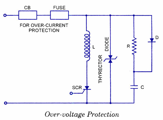
contactor, an SCR provides fast response and high resolution as well as the ability to limit current and regulate load voltage, current or power. Disadvantages to using an SCR Power Control can include low power factor, high harmonic currents and radio frequency interference (RFI) when using phase-fired power controllers.
425 AMP THREE-PHASE SCR CONTROLLER 1.0 INTRODUCTION TO SCR POWER CONTROL Since the development of SCR power controllers in the late 1950™s, the power handling capabilities of SCR™s (silicon controlled rectifiers) have advanced from a few hundred watts to many megawatts. So, too, the use of SCR power controllers in industrial applications has
PDF What You Should Know About Scr Power Controllers Circuit Diagram
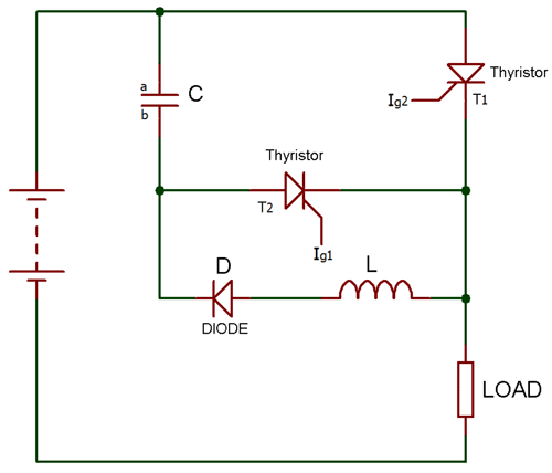
This method can be effectively used in applications requiring RMS current control or load power control. Battery Charger using SCR. Fence chargers primarily require a high voltage generator stage, where a high switching device like an SCR becomes highly imperative. SCRs thus become specifically suitable for such applications where they are